10+ 555 block diagram
Either between output terminal. The significance of each pin is self-explanatory from.

555 Timer Astable Mode Formulas Calculations Time And Frequency Circuit Timer Block Diagram
Web The 555 Timer IC is an 8 pin mini Dual-Inline Package DIP.

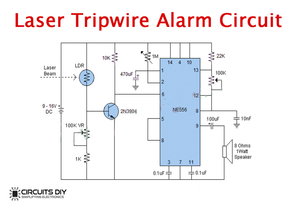
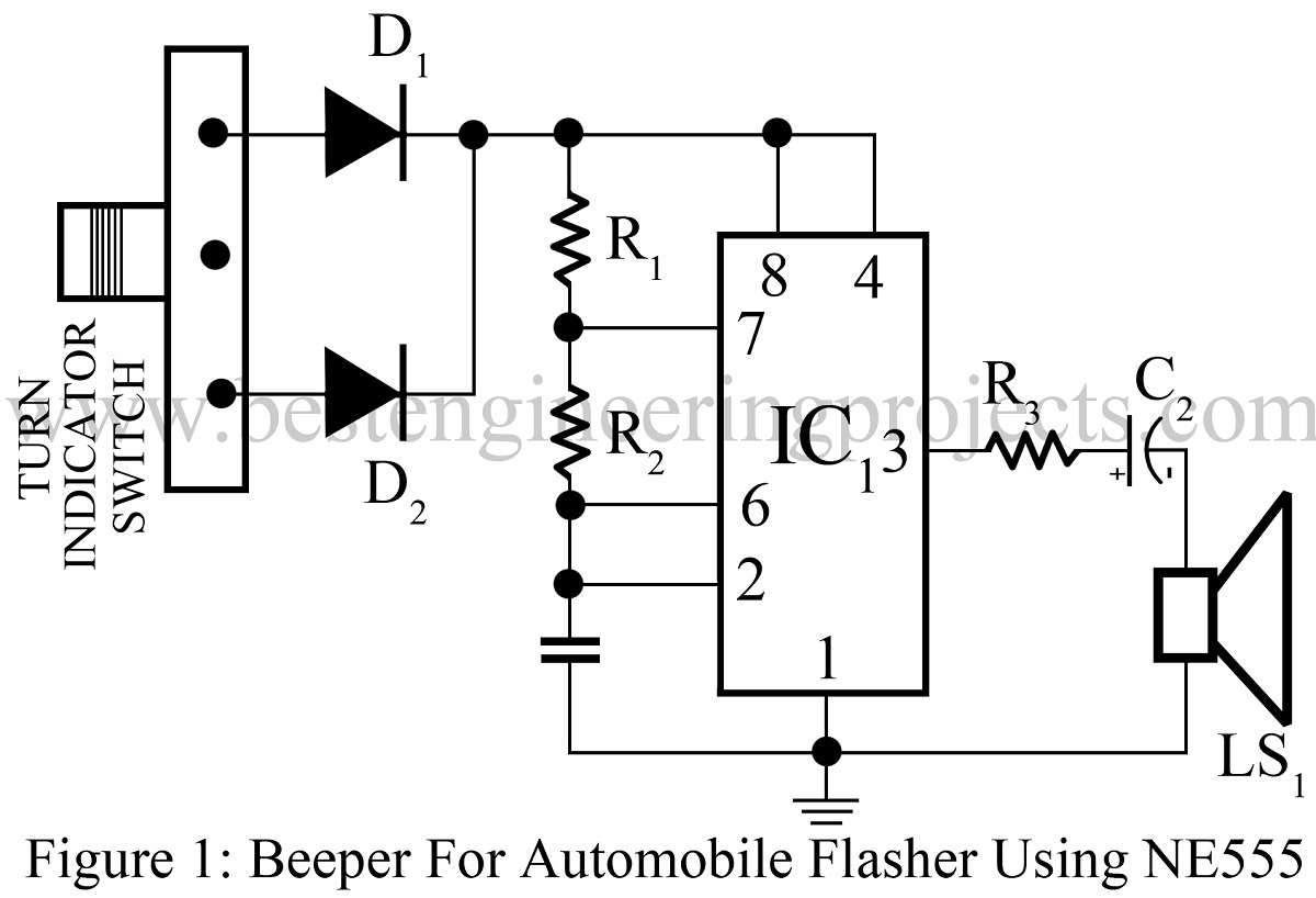
. Web In this tutorial 555 Timer IC is introduced. I hope you more understand. Web The 555 is also available in the NE556 Timer Oscillator.
555 Timer This is very popular and most common using ic used for various purposes in the electronics area. From the above figure three 5k internal resistors act as voltage divider providing bias voltage of 23 Vcc to the upper comparator 13 Vcc to the. Web Variants consist of combining multiple chips on one board.
The 555 astable multivibrator set up for a 50 duty cycle. 555 Timer IC 16 8051 26 8051 projects 21 Amplifier Circuits 39. Web The following figure shows the functional diagram of timer IC 555.
The CMOS 555 timer. Web 555 Timer Pin Diagram and Descriptions. 852019 10 GND Con V cc The 555 connections for one-shot operation.
Web Simplified block diagram of a 555 timer with the external timer components to form an Astable Multivibrator. The NE556 Timer is the combination of two individual 555 timers in 14-pin DIP package. Now as shown in figure there are eight pins for a 555 Timer IC namely 1Ground.
Block diagram 8 pin DIP configuration Pin diagram and description. As shown in figure IC555 includes two comparators one RS flip-flop and other few discrete components like. There are two ways of connecting load to output terminal.
The NE555 contains 24 bipolar transistors two diodes and 15 resistors that form six functional blocks. A block diagram rep. Choose a template Pick a block diagram template.
Web NE555 Bloc Diagramsvg. The block diagram of ADC is shown. A circuit-diagram and b waveforms.
Web The output of 555 is used to drive load controlling devices such as transistors and relays. Web The block diagram of a 555 timer is shown in the above figure. Web Look at the block diagram again.
Between the supply voltage VCC and. Let us look at the pin diagram to have an idea about the timer Integrated Circuit IC before we talk about 555 timer working. Web 555 Timer ic Tutorial.
Web Block Diagram of 555 Timer IC. However 555 is still the most popular. In short the 555 timer chip works by detecting threshold voltage levels.
Web Up to 64 cash back Launch Canva Open Canva on your desktop browser or mobile app and search for block diagram. 555 timer ic is widely used in many electronics. The pin diagram of a 555 Timer IC is shown in the following figure.
Theory of the working of this IC is discussed in detail along with its basic introduction. Web 555 timer IC block diagram pin diagram of 555 IC with all basics are covered in this videoTIME STAMPS -000 - Intro033 - What is 555 Timer IC116 - Aplica.

Ne555 74hc595 16bit 16 Channel Light Water Flowing Lights Led Module Kit Diy Kits
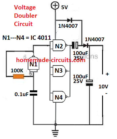
Simple Circuits Using Ic 7400 Nand Gates Homemade Circuit Projects

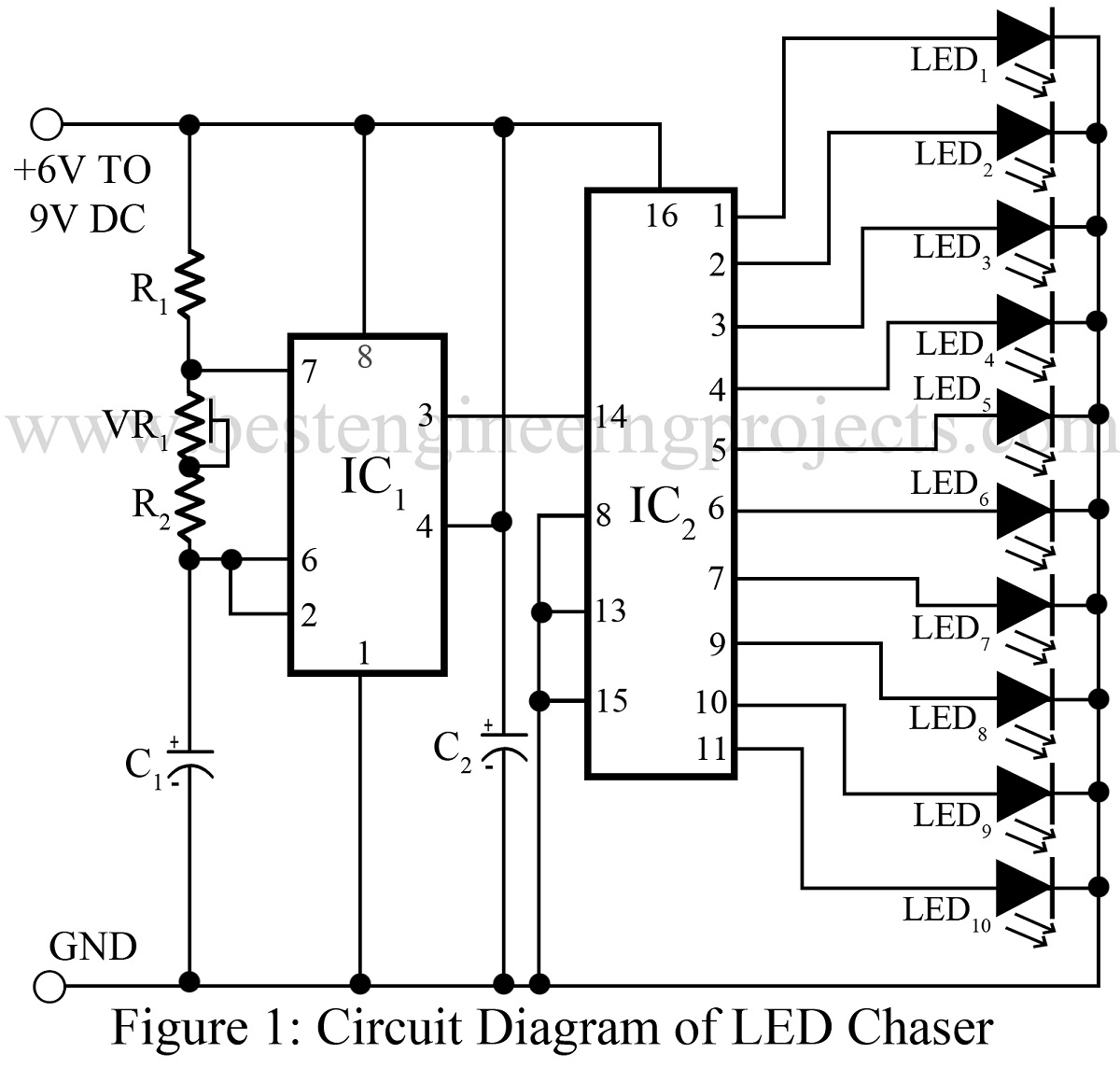
Pin On Led Circuits Projects
50 Top 555 Timer Ic Projects Engineering Projects

Pin On No 1

Pin On Electronic Stuff

50 Top 555 Timer Ic Projects Engineering Projects

Lm555cn Timer Datasheet Pinout Features Faq

How Does Ne555 Timer Circuit Work Datasheet Pinout Eleccircuit Com Electrical Circuit Diagram Electronic Circuit Projects Circuit

50 Top 555 Timer Ic Projects Engineering Projects
Top 10 Simple Electronics Projects For Complete Beginners
50 Top 555 Timer Ic Projects Engineering Projects
Top 10 Simple Electronics Projects For Complete Beginners

50 Top 555 Timer Ic Projects Engineering Projects
50 Top 555 Timer Ic Projects Engineering Projects

Pin On 555 Circuits

Ramp Timer With Powerful Light Bar The Planted Tank Forum